Installation & Debugging
Chapter 11 — Pre-installation requirements, installation procedures, construction standards, and debugging methods
A successful boundary security deployment begins long before the first device is mounted in the rack. Pre-installation verification, systematic installation procedures, and structured debugging methods are the foundation of a reliable, maintainable, and secure boundary security system. This chapter provides the complete operational reference for installation and commissioning teams.
11.1 Pre-Installation Requirements
All pre-installation requirements must be verified and documented before any boundary security device is installed. Failure to complete pre-installation verification is the most common cause of installation delays, rework, and post-deployment reliability issues. The following checklist must be signed off by both the installation team and the site owner before work begins.
| # | Pre-Check Item | Verification Method | Owner | Status |
|---|---|---|---|---|
| 1 | Rack space and weight capacity verified for all devices | Rack elevation diagram + floor load calculation | Facilities | ☐ Required |
| 2 | Dual power feeds available (A-feed and B-feed) at rack | PDU feed verification at breaker panel | Facilities | ☐ Required |
| 3 | UPS runtime meets target for full boundary device load | UPS load calculation + runtime test | Facilities | ☐ Required |
| 4 | Cooling and airflow verified; blanking panels available | Thermal mapping; blanking panel inventory | Facilities | ☐ Required |
| 5 | Grounding and surge protection validated | Ground resistance test; SPD inspection | Facilities | ☐ Required |
| 6 | OOB management network ready and isolated from production | Network diagram review; VLAN verification | Network Team | ☐ Required |
| 7 | IP plan and zone/VRF plan approved and documented | IP plan review and sign-off | Network Architect | ☐ Required |
| 8 | Routing design validated for symmetry (no asymmetric paths) | Route design review; path trace verification | Network Architect | ☐ Required |
| 9 | Certificates/PKI process ready; admin MFA enforced | PKI enrollment test; MFA verification | Security Team | ☐ Required |
| 10 | SIEM endpoints reachable; EPS and storage capacity confirmed | Connectivity test; SIEM capacity review | Security Team | ☐ Required |
| 11 | Change window approved; rollback plan written and reviewed | Change management approval; rollback plan review | Change Manager | ☐ Required |
| 12 | Firmware baseline and signature updates staged offline | Firmware version verification; offline staging | Installation Team | ☐ Required |
| 13 | Spare optics, cables, and SFP modules available on-site | Spare parts inventory check | Installation Team | ☐ Required |
| 14 | Physical security controls active (locks, CCTV, access control) | Access control test; CCTV coverage verification | Facilities | ☐ Required |
11.2 Installation Requirements
The four installation phases below must be completed in sequence. Each phase has specific requirements and acceptance criteria that must be verified before proceeding to the next phase. The accompanying photographs illustrate the correct execution of each phase.
Phase 1: Device Racking and Power Connection

Figure 11.1: Rack-Mount Installation — Technician using torque screwdriver to mount enterprise firewall appliance with ESD protection, dual PSU cables connected to A-feed (red) and B-feed (blue) PDUs, airflow direction label applied, asset tag attached
- Mount devices using rack rails; verify airflow direction matches rack cooling design (front-to-back or bottom-to-top).
- Use torque screwdriver set to manufacturer specification (typically 1.5–2.5 Nm) for all rack screws.
- Connect dual PSUs to separate A-feed and B-feed PDUs using color-coded power cords (red = A-feed, blue = B-feed).
- Apply asset tag and airflow direction sticker to each device chassis before powering on.
- Fill all unused rack units with blanking panels before powering on any devices.
Phase 2: Cabling and Labeling

Figure 11.2: Cabling and Labeling — Engineer dressing patch cords with Velcro straps, heat-shrink labels at both cable ends, color-coded zones (blue=production, red=management, green=DMZ, yellow=HA), port map documentation in hand
- Apply heat-shrink labels at both ends of every cable before installation; labels must match the port map documentation.
- Use Velcro straps for all cable bundling; never use zip ties on fiber cables (minimum bend radius violation risk).
- Color-code cables by zone: blue for production, red for management, green for DMZ, yellow for HA links.
- Maintain minimum bend radius for all cable types: 4× cable diameter for copper, 10× for fiber.
- Document every port connection in the CMDB within 24 hours of installation.
Phase 3: OOB Management Setup

Figure 11.3: OOB Management Setup — Dedicated OOB management switch, console server with labeled console cables, jump host (bastion), production and management cables physically separated with different colors and routing paths
- Connect all boundary device management ports to the dedicated OOB management switch only — never to production VLANs.
- Connect console ports to the console server using labeled console cables; verify console access before proceeding.
- Configure the bastion host (jump host) as the only administrative entry point to the OOB management network.
- Verify that management traffic is completely isolated from production traffic using VLAN verification tools.
- Test OOB access from the NOC/SOC before connecting any data interfaces.
Phase 4: HA Link Verification
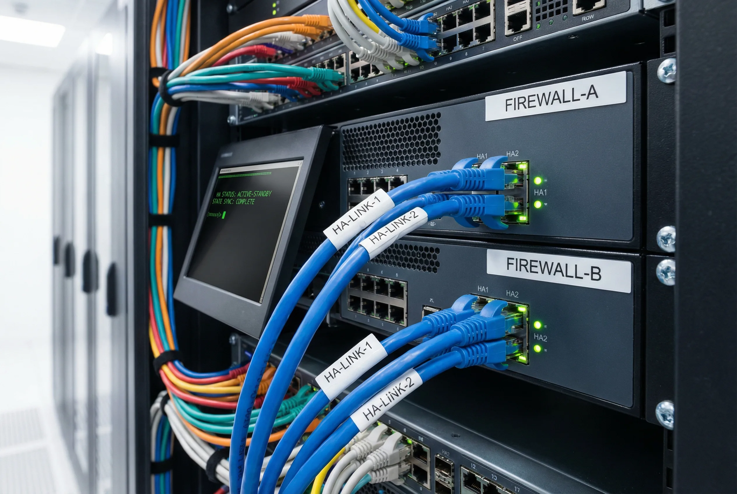
Figure 11.4: HA Link Verification — Two enterprise firewalls (FIREWALL-A and FIREWALL-B) with dedicated HA-LINK-1 and HA-LINK-2 cables on dedicated HA ports, solid green link LEDs, console showing HA STATUS: ACTIVE-STANDBY, STATE SYNC: COMPLETE
- Connect HA links using dedicated direct copper cables between HA-specific ports only — never shared with data interfaces.
- Verify both HA links show solid green link LEDs before proceeding to HA configuration.
- Confirm HA status shows ACTIVE-STANDBY and STATE SYNC: COMPLETE on console before connecting data interfaces.
- Test HA failover with traffic running before declaring installation complete.
- Document HA failover time and compare against target RTO.
Common Installation Errors and Consequences
| # | Common Error | Consequence | Prevention |
|---|---|---|---|
| 1 | Single power feed (both PSUs on same PDU or breaker) | Complete device outage on single breaker trip | Verify A/B feed separation with PDU labeling and breaker mapping |
| 2 | HA link on production VLAN or shared with data interface | Data congestion causes HA instability; false failovers | Use dedicated HA ports; verify with VLAN isolation test |
| 3 | Inside interface connected to only one core switch | Single link failure causes complete zone outage | Require LACP/MLAG to two separate core switches |
| 4 | Missing route filtering on BGP peering | Route leak exposes internal prefixes to internet | Apply prefix-lists and max-prefix limits; verify with route audit |
| 5 | WAF bypass path exists (direct origin access) | Direct exploitation of origin servers bypassing WAF | Verify no direct path to origin; test from external perspective |
| 6 | Logs sent over plaintext (no TLS on syslog) | Log tampering risk; compliance violation | Enforce syslog over TLS; verify certificate validation |
| 7 | No NTP configured or NTP not authenticated | Clock drift causes log correlation failures | Configure authenticated NTP; verify drift within threshold |
| 8 | SPAN port oversubscription (too many sources) | Packet loss in NDR detection feed; blind spots | Calculate SPAN capacity; use TAP for critical vantage points |
11.3 Construction Standards
- Cable routing: Separate power and data cables by a minimum of 50mm; maintain minimum bend radius; avoid routing cables over sharp edges or through areas with moving parts.
- Fixing and strain relief: Apply strain relief at all cable entry points; avoid placing mechanical stress on port connectors; use cable management arms for devices that slide out for maintenance.
- Labeling: Apply consistent naming convention (e.g., SITE-RACK-DEVICE-PORT) to all cables and ports; update CMDB within 24 hours of any change.
- Grounding: Bond all racks and devices to the facility ground bar; verify ground resistance ≤ 4 ohms per rack; document grounding topology.
- Spacing and thermal management: Fill all unused rack units with blanking panels; avoid blocking device intake or exhaust vents; verify inlet temperature within design range before and after installation.
- Physical protection: Apply port blockers to all unused ports immediately after installation; apply tamper seals to all chassis screws and log serial numbers.
11.4 Debugging Methods
The structured debugging workflow below ensures systematic isolation of issues, minimizes the risk of making problems worse, and produces documented evidence for post-incident review. All debugging actions must be logged with timestamps and the name of the engineer performing them.
1. Define symptom precisely (what fails, when, from where, to where)
2. Isolate scope (which zone, interface, application, or time window)
3. Verify routing symmetry (confirm traffic takes the same path in both directions)
4. Check policy hits (confirm traffic matches expected rule; look for shadow rules)
5. Validate TLS/WAF behavior (check for certificate errors, WAF false positives)
6. Confirm log pipeline (verify events are reaching SIEM; check for gaps)
7. Apply fix (document the change; use change management process)
8. Regression test (verify fix resolves symptom without breaking other functions)
9. Document findings and update runbook
| Problem Category | Typical Symptoms | Primary Debug Tools | Common Root Causes |
|---|---|---|---|
| Routing / Asymmetry | Random drops; intermittent failures; TCP resets | Traceroute; flow analysis; route table inspection | ECMP imbalance; PBR misconfiguration; missing return routes |
| Policy Mismatch | Traffic blocked unexpectedly; wrong rule matching | Policy trace; hit count analysis; packet capture | Rule ordering; shadow rules; missing NAT; zone mismatch |
| TLS / Certificate Errors | Browser SSL errors; application failures after TLS inspection | Certificate chain inspection; TLS handshake capture | Expired intermediate CA; missing root trust; cipher mismatch |
| WAF False Positives/Negatives | Legitimate traffic blocked; attacks not detected | WAF log analysis; rule tuning; signature review | Overly aggressive rules; missing custom signatures; bypass paths |
| Log Ingestion Failures | Missing log sources in SIEM; EPS drops | Syslog connectivity test; SIEM source health dashboard | TLS certificate expiry; collector storage full; EPS cap reached |
| HA Instability | Frequent failovers; split-brain; inconsistent session state | HA event log; heartbeat packet capture; firmware version check | Shared HA/data links; heartbeat threshold too low; firmware mismatch |
Rollback Procedure
- Restore last-known-good configuration from encrypted backup; verify hash before applying.
- Revert WAF policy set to previous version using version control.
- Remove emergency blocks after validation that the original issue is resolved.
- Run full regression test suite after rollback to confirm no secondary issues.
- Document rollback in change management system with root cause and lessons learned.