Scenarios & Selection
Chapter 3 — Applicability boundaries, 8 deployment scenarios, and solution mapping matrix
3.1 Applicability Boundaries
This guide is designed for organizations with complex, multi-site, or multi-cloud environments where boundary security requires systematic design rather than ad-hoc configuration. Understanding both the applicable contexts and the explicit constraints ensures that design teams apply the guide appropriately and avoid misapplication in environments where different approaches are warranted.
| Category | Details |
|---|---|
| Applicable | Multi-site enterprises; regulated industries (finance, healthcare, energy); mixed on-premises + cloud environments; partner ecosystems with B2B connectivity; organizations with exposed APIs or web applications |
| Non-applicable | Single small office with no critical data; fully managed SaaS-only organizations without custom exposure; environments where inline security is prohibited and only monitoring is allowed (use monitoring-only subset) |
| Constraints | Change windows and maintenance restrictions; legacy protocols that cannot be encrypted; TLS inspection legal or contractual restrictions; staff skill gaps; procurement lead times; data residency requirements |
3.2 Typical Deployment Scenarios
The following eight scenarios represent the most common boundary security deployment contexts encountered in enterprise environments. Each scenario includes a description of the deployment context, architectural approach, key requirements and constraints, and measurable success metrics. The scenarios are designed to be composable — most real-world deployments will implement multiple scenarios simultaneously.
A centralized egress where thousands of users access SaaS and the internet. The egress must enforce web category control, malware blocking, and prevent data exfiltration patterns while keeping acceptable latency. The architecture typically includes dual ISP, edge routers, NGFW HA, DNS security, optional secure web gateway or cloud proxy integration, and SIEM logging. Split egress for guest Wi-Fi is strongly recommended to prevent guest traffic from traversing the same inspection path as corporate users.
Operationally, the largest risks are rule sprawl and bypass via hardcoded DNS or direct IP access. Policies must be identity-aware and time-bound for exceptions. Regular rule reviews with automated expiry enforcement are essential to prevent the accumulation of overly permissive rules that erode the security posture over time.

Figure 3.1: Internet Egress HQ — Dual NGFW appliances with redundant PDU connections, ToR switches, and OOB management in a professional data center rack
Key Requirements: Dual ISP with BGP or SD-WAN failover; TLS inspection policy defined (what/where/why); DNS security enforced with external resolver blocking; user identity mapping via agent or IdP; guest network isolation; bandwidth sizing to 95th percentile plus growth; web policy with least privilege for admin tools; central logging with EPS budget.
Branches use local internet breakout to reduce latency to SaaS applications. SD-WAN overlays connect branches to HQ and data centers. Security must be consistent across all sites despite limited local IT staff. A common solution combines SD-WAN edge with integrated security features or a branch NGFW, centrally managed policies, and cloud-based security for web filtering. ZTNA replaces full-tunnel VPN for many application access patterns.
Risks include inconsistent policy versions across branches and insufficient bandwidth for TLS inspection at smaller sites. Policy templates and inheritance mechanisms are essential to ensure that branch security posture matches the corporate baseline without requiring local configuration expertise. Remote management and zero-touch provisioning significantly reduce deployment time and error rates.
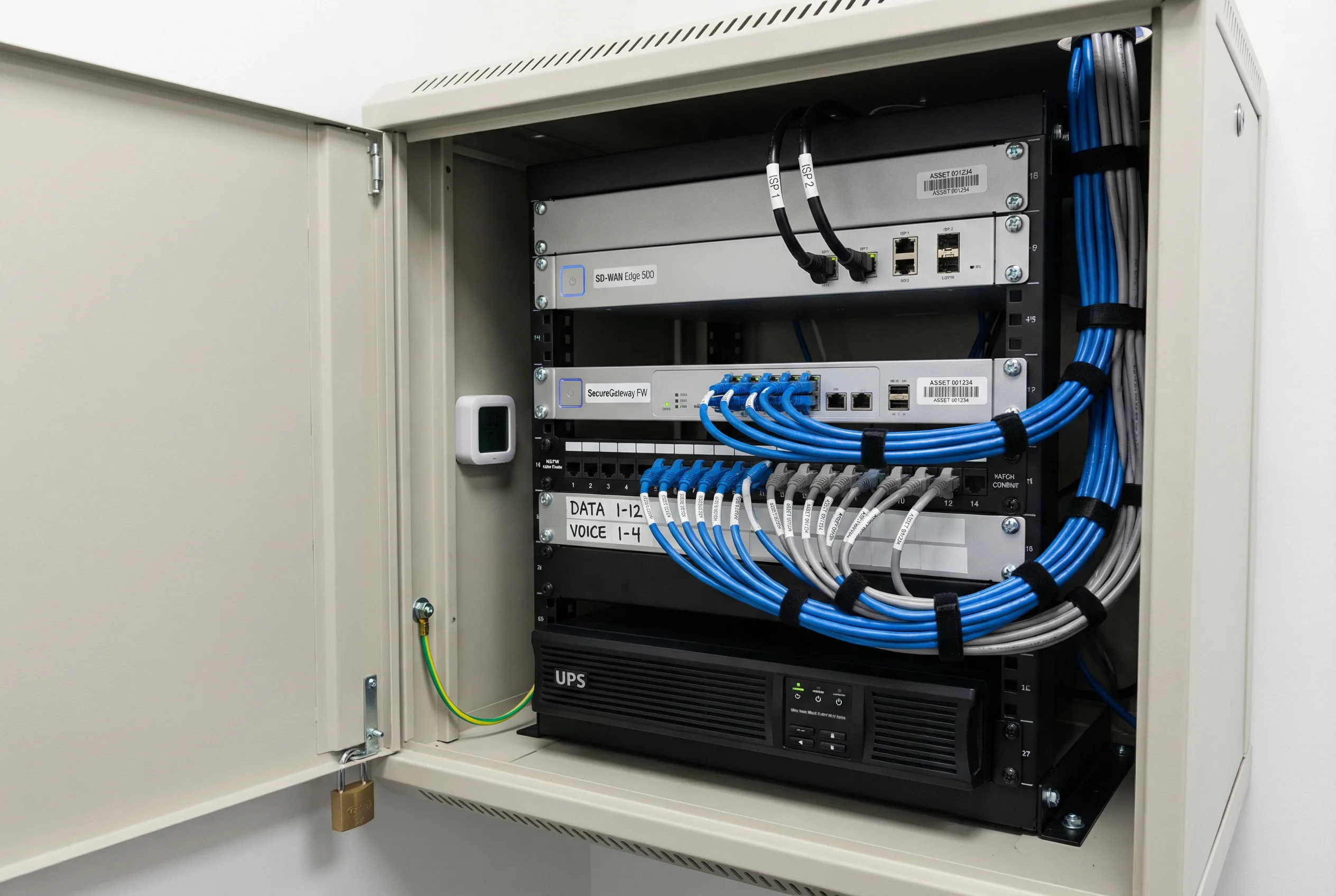
Figure 3.2: Branch Internet Breakout — Wall-mounted rack with SD-WAN appliance, compact NGFW, labeled patch panel, UPS, and dual ISP connections in a locked wiring closet
Key Requirements: Central management with zero-touch provisioning; minimal on-site configuration changes; bandwidth monitoring with alerting; local survivability mode; standardized device replacement process; standardized cabling and labeling; secure boot verification; remote logging with backpressure protection.
Public web services hosted in the data center require DMZ segmentation to protect internal systems from direct internet exposure. WAF protects HTTP/S traffic at the application layer, while NGFW enforces L3–L7 controls and NAT. DDoS mitigation is provided upstream via a scrubbing service or on-premises appliance. The design must define DMZ tiers — edge DMZ, application DMZ, and management — ensuring no direct path from the internet to internal databases without strict rules and application-layer gateways.
Operational emphasis is on secure certificate management, vulnerability patching windows, and documented emergency block procedures. The WAF must operate in a positive security model for critical applications, with a defined process for updating rules when applications change. Regular penetration tests validate the DMZ design against current threat techniques.
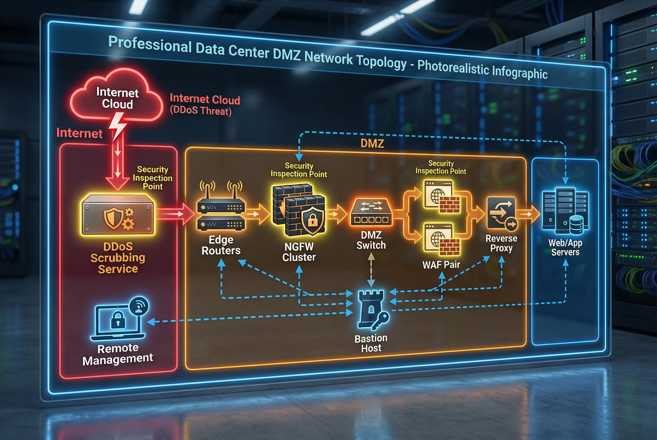
Figure 3.3: DC North-South DMZ — Internet → DDoS scrubbing → Edge routers → NGFW cluster → DMZ switch → WAF pair → Reverse proxy → Web/App servers, with isolated management via bastion host
Key Requirements: WAF positive security model for critical apps; separate DMZ switching infrastructure; no shared admin credentials; secure CI/CD IP allowlists; backend health checks; DDoS runbook with tested diversion; log retention per compliance requirements; periodic penetration tests.
Cloud workloads expose APIs and services to the internet. Controls must combine cloud-native security groups and NACLs with a centralized cloud firewall (FWaaS), WAF, API gateway, and cloud DDoS protection. The key architectural principle is consistent zoning: public subnet, private subnet, shared services, and management account. A transit gateway or hub-spoke topology centralizes traffic inspection and policy enforcement across all VPCs and accounts.
Infrastructure as Code (IaC) is mandatory for cloud security configurations to enable drift detection, version control, and automated compliance validation. Cross-region disaster recovery design must be included from the start, as retrofitting DR into cloud security architectures is significantly more complex than designing it in from the beginning.

Figure 3.4: Cloud Edge Hub-Spoke — Hub VPC with Transit Gateway, centralized inspection VPC with FWaaS endpoints, production spoke VPCs, management account, WAF at internet edge, and Private Link to SaaS services
Key Requirements: Multi-account governance with centralized policy; IaC for all security configurations; cloud flow logs enabled on all VPCs; KMS key management for data at rest; egress controls to prevent data exfiltration; private endpoints for internal services; cross-region DR design; shared responsibility matrix documented.
Vendors require limited access to specific internal applications such as ERP support portals or industrial control systems. The design replaces broad VPN access with ZTNA per-application access, just-in-time (JIT) account provisioning, and mandatory session recording. MFA is required for all vendor sessions, and device posture checks ensure that vendor devices meet minimum security requirements before access is granted.
Contract-based security requirements must specify MFA, device posture, time-bound access windows, approval workflows, session recording, and data egress restrictions. Vendors must not have direct access to management planes or administrative interfaces. Break-glass procedures for emergency vendor access must be documented and tested, with automatic session termination and audit trail generation.
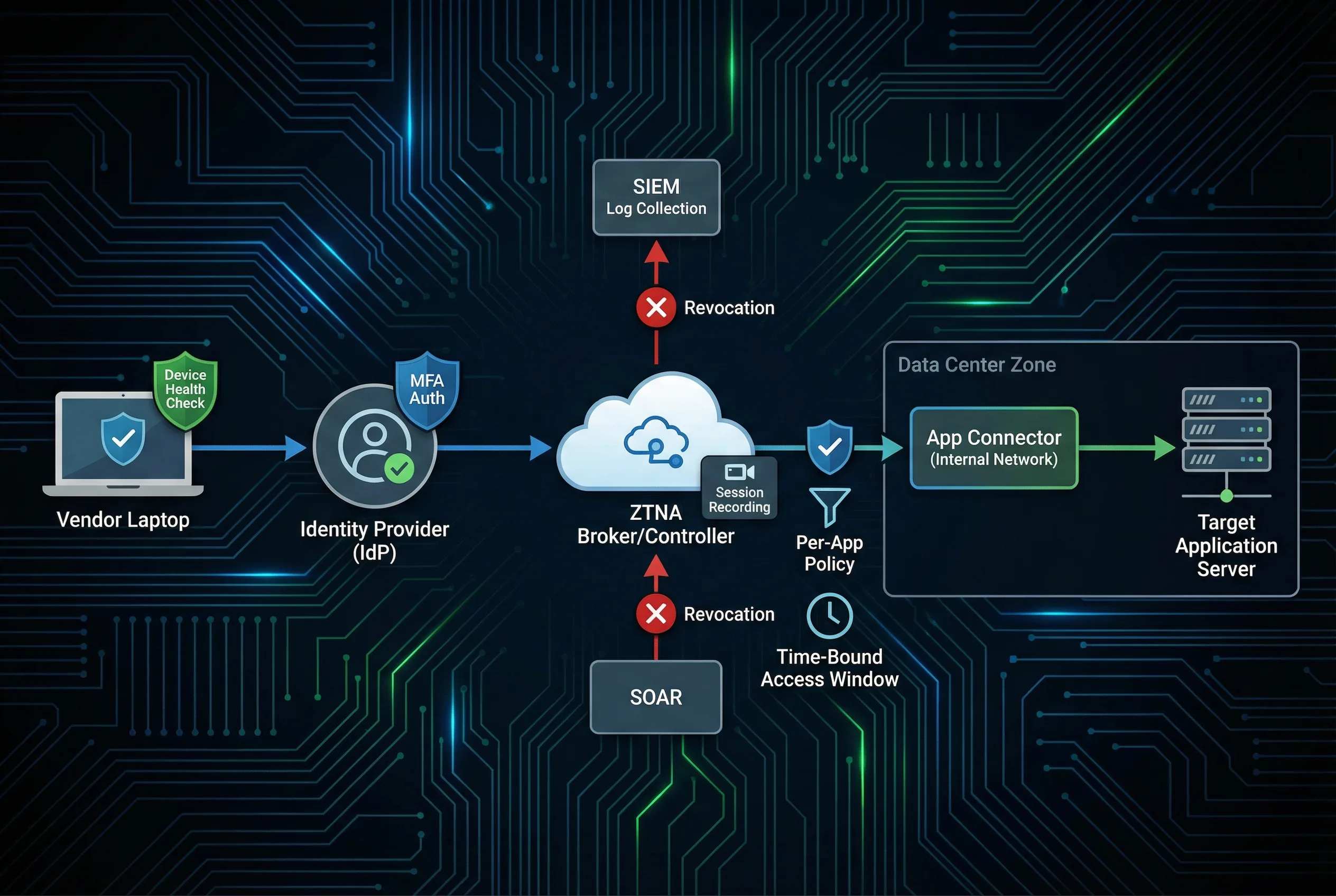
Figure 3.5: Third-Party Vendor Access — Vendor device → IdP MFA → ZTNA broker (session recording) → per-app policy → app connector → target application; SIEM log collection and SOAR token revocation
Key Requirements: Vendor identity federation with corporate IdP; MFA mandatory for all sessions; time-bound access windows with automatic expiry; approval workflow with manager sign-off; session recording with searchable index; command-level control for privileged sessions; data egress restriction; documented break-glass procedure.
Partners connect via MPLS, IPsec, or direct connect circuits. The fundamental design principle is to treat all partner networks as untrusted, isolating them into a dedicated partner VRF or security zone with strict allowlists and protocol validation. Route filtering prevents route leaks that could expose internal network topology to partner networks or allow unintended traffic flows. IPsec encryption provides confidentiality and integrity for traffic traversing shared infrastructure.
Operational processes must include a formal partner onboarding checklist, documented circuit IDs and contact information, and a defined decommission process for when partnerships end. Monitoring must detect anomalous traffic patterns from partner networks, and bandwidth commitments must be enforced to prevent one partner from impacting others.

Figure 3.6: B2B Extranet & OT Boundary — Dedicated partner zone with IPsec gateway, route filtering, and strict protocol allowlists; OT/ICS Purdue Model with industrial DMZ and data diode for one-way data transfer
Key Requirements: Strict route filtering with prefix lists; IPsec crypto baseline (AES-256, SHA-256 minimum); partner change notification process; continuous monitoring with anomaly detection; bandwidth commitment enforcement; SLA documentation; formal onboarding checklist; documented decommission process.
Operational technology networks require strict segmentation from IT networks, with only the minimum required protocols allowed across the boundary. Many legacy OT protocols such as Modbus and DNP3 cannot be encrypted, requiring compensation through isolation, passive monitoring, and strict physical access controls. The Purdue Model provides the foundational architecture, with an industrial DMZ at Level 3.5 serving as the security boundary between IT and OT zones.
Safety impact analysis is mandatory before making any changes to OT boundary controls, as incorrect configurations can affect physical processes and create safety hazards. Maintenance windows must be coordinated with operations teams, and offline patching procedures must be documented for systems that cannot be patched during normal operations. Vendor access to OT systems requires additional controls beyond standard IT vendor access procedures.
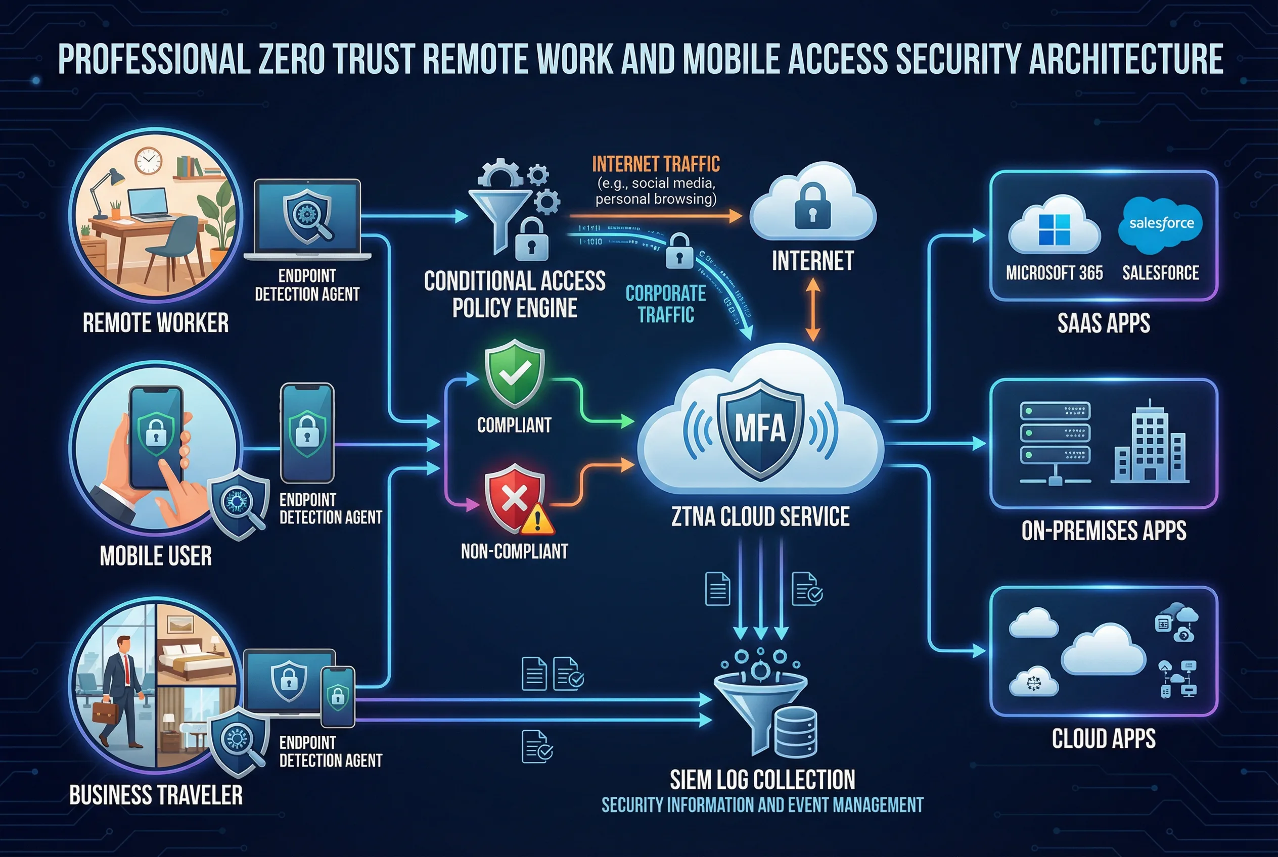
Figure 3.7: OT/IoT Boundary & Remote Access — OT DMZ with data diode and unidirectional gateway separating IT and OT zones; Zero Trust remote access architecture for mobile workers and business travelers
Key Requirements: OT DMZ with data diode or unidirectional gateway; protocol allowlist enforced at boundary; passive monitoring via network TAP (no inline inspection); maintenance window coordination with operations; vendor access controls with physical supervision; physical security for OT network access points; safety impact analysis for all changes; offline patching procedures.
Large enterprises with multiple sites require consistent security policy enforcement across headquarters, regional hubs, and branch offices, while shared internal platforms must provide tenant isolation for multiple business units. The SD-WAN and SASE architecture provides consistent policy enforcement regardless of user location or traffic destination. Centralized policy management at HQ ensures that all sites operate with the same security baseline, with local breakout for internet traffic reducing backhaul costs and latency.
For shared internal platforms, tenant isolation via VRFs or VPCs prevents one business unit from accessing another's data or services. API gateway controls enforce per-tenant rate limits and authentication, while east-west micro-segmentation prevents lateral movement within the shared platform. Audit logs must be segregated per tenant to support independent compliance reporting.
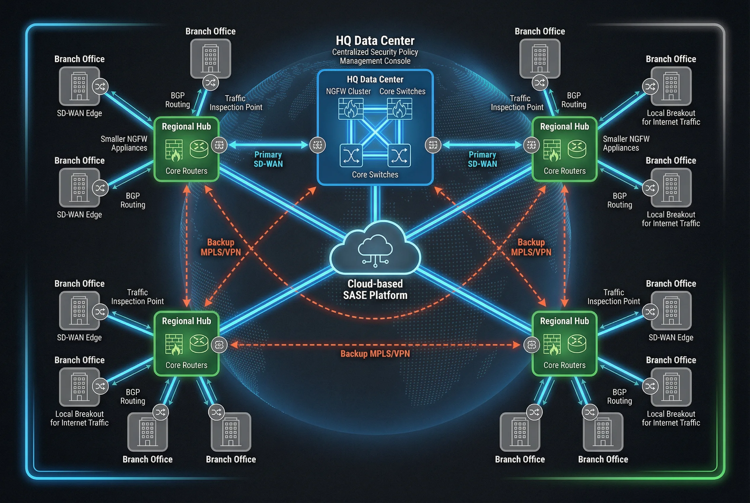
Figure 3.8: Multi-Site Enterprise WAN — HQ data center with NGFW cluster, regional hubs with smaller NGFWs, branch offices with SD-WAN edges, cloud-based SASE platform, and backup MPLS/VPN connections
Key Requirements: Tenant VRFs or VPCs with strict isolation; API authentication for all inter-tenant calls; per-tenant rate limits enforced at API gateway; secrets management with rotation; segregated audit logs per tenant; separation of admin roles (no cross-tenant admin); capacity reservation per tenant; documented incident blast-radius control procedures.
3.3 Scenario → Solution Mapping Matrix
The following matrix maps each deployment scenario to its recommended enforcement mechanisms, exposure defense controls, remote and third-party access approach, detection capabilities, and key operational notes. This matrix serves as a quick reference for design teams selecting controls for specific deployment contexts.
| Scenario | Recommended Enforcement | Exposure Defense | Remote / 3rd Party | Detection | Notes |
|---|---|---|---|---|---|
| HQ Egress | NGFW HA + DNS security | Optional SWG | ZTNA for admins | SIEM + NDR | Strong policy governance required |
| Branch Breakout | Branch NGFW or SD-WAN security | Cloud proxy optional | ZTNA | SIEM | Template-driven management |
| DC DMZ | NGFW + DMZ segmentation | WAF + DDoS | Bastion + ZTNA | SIEM + IDS | Strict inbound publish controls |
| Cloud Edge | Cloud FWaaS + SG/NACL | WAF/API + DDoS | ZTNA | Cloud logs + SIEM | IaC + drift detection mandatory |
| Vendor Access | ZTNA app connectors | N/A | JIT + MFA | SIEM | Session recording mandatory |
| B2B Extranet | Dedicated partner zone FW | Optional WAF | IPsec + allowlist | SIEM | Route filtering essential |
| OT/IoT | OT DMZ + data diode | Protocol allowlist | Supervised vendor access | Passive IDS via TAP | Safety impact analysis required |
| Multi-Site / Multi-Tenant | SASE + per-tenant FW | API gateway + WAF | ZTNA | SIEM + NDR | Tenant isolation tests mandatory |