Support & Integration
Chapter 7 — Supporting systems, cross-system interfaces, KPIs, and physical interface inventory
The boundary security system does not operate in isolation. It depends on a set of supporting infrastructure systems that provide power, cooling, physical security, network underlay, and operational services. Failures in any of these supporting systems can directly cause boundary device outages or security control failures. This chapter defines the requirements for each supporting system, their integration interfaces with the boundary security stack, and the failure chains that must be understood and mitigated.
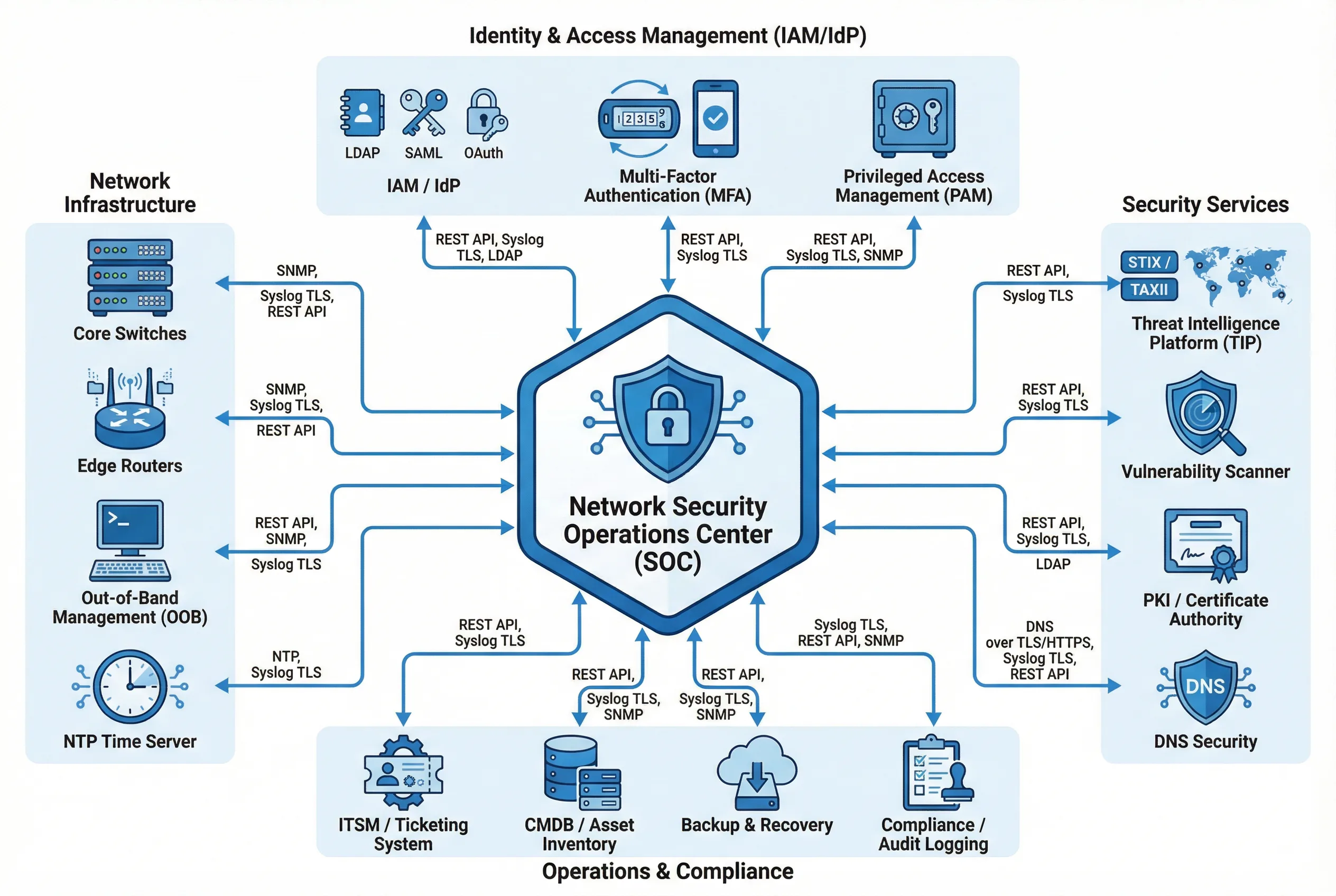
Figure 7.1: Support & Integration Ecosystem — All supporting systems integrated into a single diagram: Identity & Access Management (top), Network Infrastructure (left), Security Services (right), and Operations & Compliance (bottom), all connected to the central Security Operations Center (SOC) with labeled integration protocols
7.1 Supporting System Requirements
| System | Necessity | Capacity Guidance | Failure Risk | Acceptance Criteria |
|---|---|---|---|---|
| A. Communication & Network | Provides stable underlay for boundary devices and NDR sensors | Uplinks sized at ≥ 2× peak; SPAN/TAP capacity planned for NDR | Oversubscription causes packet drops; poor labeling delays recovery | Cable labeling audit; link redundancy test; SPAN/TAP capacity verification |
| B. UPS (Uninterruptible Power Supply) | Provides battery backup during power transitions and outages | Total load × 1.3 headroom; runtime 10–30 minutes for boundary stack | Single feed causes boundary outage; battery aging untracked leads to runtime collapse | Transfer test (≤ 10ms); battery health report; runtime test under full load |
| C. Power Distribution (PDUs) | Distributes power from UPS to individual devices with metering | Breaker utilization ≤ 80%; per-rack power budget documented | Overload trips breaker; miswired A/B feeds create hidden single point of failure | Breaker mapping verification; outlet test; per-outlet load measurement |
| D. Lightning Protection & Grounding | Protects against surge damage and reduces electromagnetic interference | SPDs at all entry points; grounding resistance ≤ 4 ohms per rack | Surge damage to transceivers and NICs; EMI causing link errors | Ground resistance measurements; SPD inspection; bonding continuity test |
| E. Data Room Infrastructure | Provides physical environment for equipment: racks, cooling, containment | Inlet temperature within design range (18–27°C); hot/cold aisle containment | Overheating triggers device throttling or reboot; airflow bypass causes hotspots | Thermal mapping under full load; blanking panel audit; airflow smoke test |
| F. Fire Protection Linkage | Protects equipment from fire without water damage | Clean agent suppression system; smoke detection with BMS integration | Fire damage to boundary devices; suppression system false activation | Alarm linkage test; emergency shutdown interface verification; procedure review |
| G. Physical Security (ACS, CCTV) | Protects boundary devices as critical security infrastructure | Badge reader at all entry points; CCTV covering all rack rows | Unauthorized physical access enables cable manipulation or device compromise | Access rights review; CCTV retention verification (≥ 90 days); forced-open alarm test |
7.2 Cross-System Interfaces & Integration
The boundary security system integrates with multiple external systems through defined interfaces. Each integration must be designed with appropriate security controls, monitored for availability, and tested during acceptance. The table below defines the integration requirements for each external system, including the protocol, security controls, and failure impact.
| System | Interface Type | Data Exchanged | Protocol | Security Controls | Failure Impact |
|---|---|---|---|---|---|
| SIEM | Log ingestion | FW/WAF/ZTNA logs, events, flows | Syslog over TLS / REST API | mTLS, RBAC, log integrity | Loss of detection and audit capability |
| ITSM | Incident/change ticketing | Incidents, change requests, approvals | REST API / Webhook | OAuth 2.0, RBAC | Untracked changes; delayed incident response |
| IdP (Identity Provider) | Authentication and authorization | MFA tokens, SSO assertions, user claims | SAML 2.0 / OIDC | MFA mandatory, conditional access policies | Admin access disruption; authentication failures |
| NTP | Time synchronization | Time reference signals | NTPv4 with authentication | Allowlist, NTP authentication keys | Log correlation failures; certificate validation errors |
| PKI / CA | Certificate management | Certificate issuance and renewal | ACME / REST API | RBAC, approval workflow | TLS inspection failures; expired certificates |
| BMS / Environmental | Environmental monitoring | Temperature, humidity, power alarms | SNMP v3 / REST API | Management zone segmentation | Missed overheating or power events |
| UPS / PDU | Power telemetry | Load, runtime, battery health | SNMP v3 / Modbus gateway | Management zone only; no production VLAN | No power visibility; undetected battery degradation |
| Threat Intelligence | IOC and threat feed ingestion | IP/domain/hash indicators, STIX bundles | STIX/TAXII / REST API | API key auth, TLS, feed validation | Reduced detection of known threats |
7.3 Supporting System Mechanisms, KPIs & Failure Chains
| System | Key Mechanism | KPI | Failure Chain |
|---|---|---|---|
| UPS | Battery health monitoring → runtime assurance → prevents abrupt shutdown | Battery health ≥ 80%; runtime ≥ 15 minutes at full load | Battery degradation → runtime collapse → firewall shutdown → site outage |
| Cooling | Airflow management + hot/cold aisle containment → stable inlet temperatures | Inlet temperature 18–27°C; no hotspots above 35°C | Fan failure → hotspot → device thermal throttling → reboot → failover overload |
| Physical Security | Access logs + tamper seals → deterrence and detection of unauthorized access | 100% access events logged; 0 unresolved tamper seal discrepancies | Unauthorized access → cable manipulation → outage + possible device compromise |
| NTP | Authenticated time sync → consistent timestamps across all devices | All devices within 1 second of reference; drift alert threshold 100ms | NTP failure → clock drift → log correlation failures → missed attack detection |
| PKI | Automated certificate renewal → prevents TLS inspection failures | Certificate expiry alerts ≥ 30 days before expiry; 0 expired certificates | Certificate expiry → TLS inspection failure → encrypted traffic bypasses security |
7.4 Physical Interface Inventory
The physical interface inventory documents all connection types between boundary devices, their typical connectors, locations, and purposes. Common installation errors are documented alongside their consequences to guide installation teams and acceptance testers.
| Interface | Typical Connector | Location | Purpose | Common Installation Error | Consequence |
|---|---|---|---|---|---|
| ISP Uplink | Fiber LC/SC or Copper RJ45 | Router WAN ports | Internet access and BGP peering | Single-path fiber from single ISP | Single point of failure for all internet traffic |
| FW Inside Links | 10/25/40G SFP+/QSFP+ | NGFW ↔ Core switches | Internal zone routing and enforcement | No LACP/MLAG; single link only | Link failure causes complete outage for all internal zones |
| FW HA Links | Direct copper Cat6A | FW-01 ↔ FW-02 dedicated ports | HA heartbeat and state synchronization | HA link shared with data traffic interface | Data congestion causes HA instability and false failovers |
| OOB Management | 1G copper RJ45 | All devices ↔ OOB management switch | Out-of-band administrative access plane | Management port connected to production VLAN | Increased exposure; management access blocked by firewall policy |
| TAP / SPAN | TAP (passive optical/copper) or SPAN port | Core switches and DMZ switches | NDR sensor visibility at key vantage points | SPAN port oversubscription; too many sources on one SPAN | Packet loss in detection feed; NDR misses attack traffic |